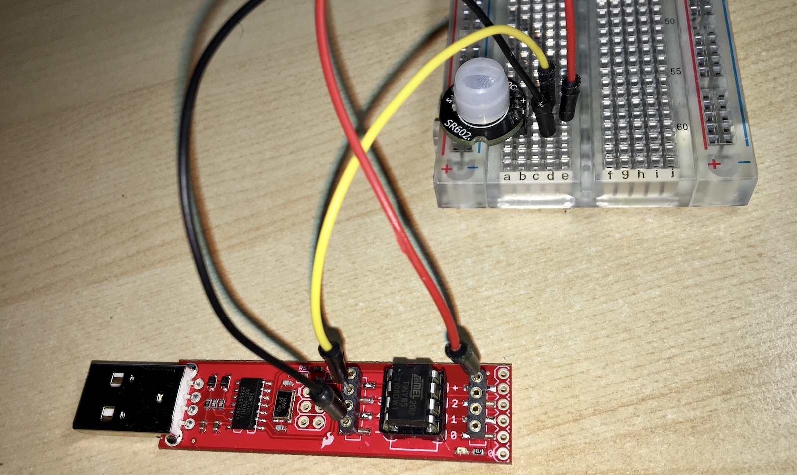
I had a hard time getting started with ATtiny85. I ordered a few of those chips to use in a motion detector for my backyard because of its low power consumption and ability to be put into a deep sleep and woken up via an interrupt. The interrupt in this case would be a rising or falling edge of a PIR sensor signal.
I have switched to using arduino-cli over Arduino IDE a while ago since I much prefer command line based tools and text editors.
Here are the steps needed to set it up:
- Hardware
- Add
arduino-clisupport for ATtinyX4/ATtinyX5 boards - Compiling the blink sketch
- Compiling code with interrupts and deep sleep
Fun fact, the sample code at the bottom of this post with the hardware listed below uses less than 300uA to run and detect motion.
Hardware
- ATtiny85-20U
- Sparkfun Tiny AVR Programmer
- SR602 PIR motion sensor
Add arduino-cli support for ATtinyX4/ATtinyX5 boards
First, let’s see if your current configuration supports ATtiny family:
$ arduino-cli board listall | grep -i attiny
Nothing… Now, let’s check what additional boards we have installed using arduino-cli config dump option:
$ arduino-cli config dump
board_manager:
  additional_urls:
  - https://arduino.esp8266.com/stable/package_esp8266com_index.json
...
Let’s add the popular ATtinyX4/5 cores package from this repo and install attiny:avr cores.
$ arduino-cli config add board_manager.additional_urls https://raw.githubusercontent.com/damellis/attiny/ide-1.6.x-boards-manager/package_damellis_attiny_index.json

$ arduino-cli core update-index
Updating index: package_index.json downloaded
Updating index: package_index.json.sig downloaded
Updating index: package_esp8266com_index.json downloaded
Updating index: package_damellis_attiny_index.json downloaded

$ arduino-cli core search attiny
ID         Version Name
attiny:avr 1.0.2   attiny

$ arduino-cli core install attiny:avr
Downloading packages...
attiny:avr@1.0.2 already downloaded
Installing attiny:avr@1.0.2...
Configuring platform...
attiny:avr@1.0.2 installed

$ arduino-cli board listall | grep -i attiny
ATtiny24/44/84                   attiny:avr:ATtinyX4
ATtiny25/45/85                   attiny:avr:ATtinyX5
I have the ATtiny85 chip so I will be using attiny:avr:ATtinyX5 as the board command line parameter going forward.
Compiling the blink sketch
First, let’s compile and upload a simple blink sketch.
#define LED_BUILTIN PB0
void setup() {
  pinMode(LED_BUILTIN, OUTPUT);
}
void loop() {
  digitalWrite(LED_BUILTIN, HIGH);
  delay(1000);
  digitalWrite(LED_BUILTIN, LOW);
  delay(1000);
}
Since attiny:avr:ATtinyX5 covers a family of chips we’ll also need to specify the cpu and clock speed. If you notice that your delay commands are not matching the expected time, you probably got the clock speed wrong. By default ATtiny seems to run at 1MHz, which is very low power mode. We need to include clock=internal1 so our code matches that frequency.
$ arduino-cli compile --fqbn attiny:avr:ATtinyX5:cpu=attiny85,clock=internal1 blink
$ arduino-cli upload --fqbn attiny:avr:ATtinyX5:cpu=attiny85,clock=internal1 --programmer usbtinyisp blink
You can check all available options by running arduino-cli board details command:
$ arduino-cli board details -b attiny:avr:ATtinyX5
Board name:            ATtiny25/45/85
FQBN:                  attiny:avr:ATtinyX5
Board version:         1.0.2

Package name:          attiny
Package maintainer:    David A. Mellis
Package URL:           https://raw.githubusercontent.com/damellis/attiny/ide-1.6.x-boards-manager/package_damellis_attiny_index.json
Package website:       https://github.com/damellis/attiny

Platform name:         attiny
Platform category:     attiny
Platform architecture: avr
Platform URL:          https://github.com/damellis/attiny/archive/6bba7d452af59d5190025bc870ec9e53d170e4d9.zip
Platform file name:    6bba7d452af59d5190025bc870ec9e53d170e4d9.zip
Platform size (bytes): 5913
Platform checksum:     SHA-256:1654a8968fea7d599255bd18430786f9c84340606e7a678b9cf9a3cd49d94ad7

Option:                Processor                                                                                                cpu
                       ATtiny25                                                                                            ✔    cpu=attiny25
                       ATtiny45                                                                                                 cpu=attiny45
                       ATtiny85                                                                                                 cpu=attiny85
Option:                Clock                                                                                                    clock
                       Internal 1 MHz                                                                                      ✔    clock=internal1
                       Internal 8 MHz                                                                                           clock=internal8
                       Internal 16 MHz                                                                                          clock=internal16
                       External 8 MHz                                                                                           clock=external8
                       External 16 MHz                                                                                          clock=external16
                       External 20 MHz                                                                                          clock=external20
Programmers:           Id                                                                                                  Name
Your sketch should now be uploaded and blinking the Sparkfun’s programmer’s built in LED.
Compiling code with interrupts and deep sleep
#include <avr/io.h>
#include <avr/interrupt.h>
#include <avr/sleep.h>

#define LED_PIN       PB0
#define TRIGGER_PIN   PB3

ISR(INT0_vect) {
  GIMSK = 0;                     // disable external interrupts (only need one to wake up)
}

void setup() {
  pinMode(LED_PIN, OUTPUT);
  pinMode(TRIGGER_PIN, INPUT);
}

void loop() {
  // I am only using delay function for this example purposes
  for(byte i=0; i<3; i++) {
    digitalWrite(LED_PIN, HIGH);
    delay(100);
    digitalWrite(LED_PIN, LOW);
    delay(100);
  }

  set_sleep_mode(SLEEP_MODE_PWR_DOWN);
  sleep_enable();

  MCUCR &= ~bit(ISC01);                     // enable interrupt on logic level change
  MCUCR |= bit(ISC00);                      //

  GIMSK |= bit(PCIE);                       // enable interrupts with Pin Change from the default PB2
  PCMSK |= bit(PCINT3);                     // enable interrupt on pin 3

  sleep_cpu();                              // go to sleep

  sleep_disable();                          // wake up here
}
Leave a Reply